

Ecologically clean generation of electric power with help of linear generators
© Ioffe Alexander
For contact: ioffe.shura@yandex.ru
Recently, when the problem of use of ecologically clean sources of electric energy is burning issue, the author of this article hope to demonstrate, that it’s will be possible to use fuller and more comfortable such suppliers of ecologically clean electric energy as wind and waves, and results of human activities, for example, vibration and shaking of means of transport and traffic-bearing surface, when we shall use along with electrical generators, which work from rotation, another type of generators, which work from forward movements – linear generators. In some situations the author proposes to use effective, in his opinion, ways of transformation of linear movements to the rotation for use with usual dynamos.
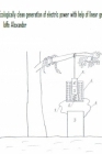
First linear converters of energy were built in the early nineteenth century (they were demonstrated in works of Faraday and Lenz) and these generators were solenoids with constantly moving magnets inside. But these devices were in use only in scientific laboratories for formulation of laws of electromagnetism. Further were used meaningfully only generators, which worked from rotation. But now mankind is remembering “long forgotten old things”. For example, recently were built “eternal” or “inductive Faraday’s flashlights” (see the ill. 1),* which work from shaking, and they are based on “linear generator” – solenoid with vacillating permanent magnet inside**, and rectifying system, smoothing element and accumulator. In the internet you can find description of building of such generator for supplying bike lights; such generators work on the same principle – from magnet’s moving inside a solenoid (shaking is caused by bike and not by men).
Ill. 1. “Faraday’s flashlight”.
1 – magnet,
2 – solenoid,
3 – springs,
4 – partition,
5 – lamp.
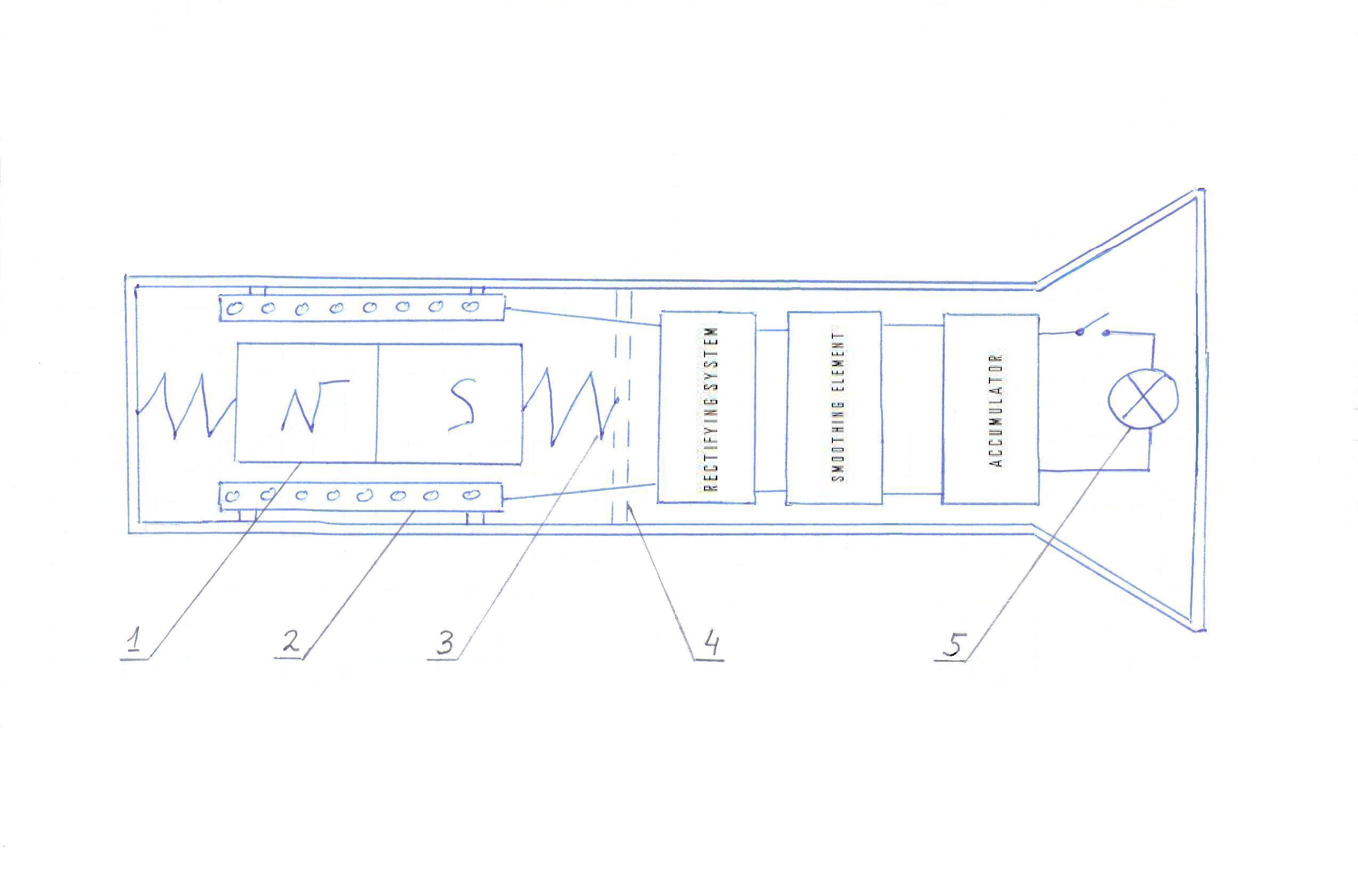
Now exist and are designed generators, in which is used a “piezoelectric effect” – the capability of some crystals for a generation of electricity by deformation (see the ill.2).
Ill. 2. A generator with piezoelectric crystals. 1 – metallic plates, 2 – piezoelectric crystal.
For example, all know lighters with piezoelectric crystals. French scientists (specifically, Jean-Jacques Chailout at Innovations Centre in Grenoble) have decided to put modules with piezoelectric crystals (PVDF) under raindrops and in such a way to generate electric energy. The Israeli firm “Innowatech” is working at the generation of electric energy from pressure of cars on traffic-bearing surfaces – piezoelectric crystals will be put under roads. In the Netherlands scientists are planning “to accumulate” energy under dancing’s floor.
All examples above, except the energy of raindrops, are related to human activities. It’s possible to propose to place linear generators into bumpers of autos and trains (there is better to use generators with solenoids, because they will be do the part of a work of bumpers***) and to put on all these vehicles enlarged copies of bicycles’ generators, which were represented above and which work from a shaking, and, additionally, to put linear generators (better with piezoelectric crystals for less shifts) under rails of railways.
Consider now, how to use fuller the energy of wind. There are known electrical wind generators: a wind rotates airscrews and airscrews rotate axles of dynamos. But airscrews are not always comfortable for an using. If they are used in housing estates, they demand additional place and must be confined in nets for security. They can spoil the appearance, obscure sun and impair a view. It’s hard to build rotating generators: they demand good bearings and a balancing of rotating parts (for preventing a breaking). And at parked electromobiles such generators will create temptation for thieves and vandals.
In this work I propose to use more comfortable working bodies, which are influenced by wind: shields, plates, sails, “natural wind collectors” (about this will be spoken below), inflatable figures. And in place of dynamos I propose to use specific fastenings: in linear generators energy will be generated from mechanical shifts and a pressure of working bodies. In such fastenings we can use piezoelectric crystals and solenoids with mobile magnetic cores. The electrical power, generated by this fastenings, will be gone through rectifiers and smoothing elements and will charge accumulators for further use of generated energy. It’s simple to produce all parts of such linear generators.
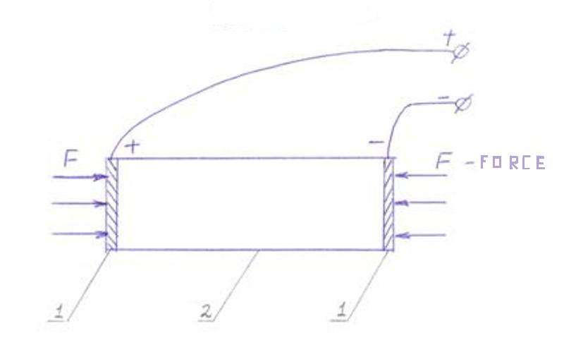
Shields with such fastenings (see the ill. 3a, b) placed at houses walls and balconies walls will be very advantageous and without any discomfort: sound proofing and thermal insulation, shadow. They practically don’t demand additional space. Advertisement hoardings, sun canopies, shelters from rain with such modules with piezoelectric crystals for raindrops will not only fulfill its function, but will generate electric power too (see the ill.4). On the same principle we can make “work” any fence.
Ill. 3. A - a solenoids linear generator with shields as a working body, B – linear generators with piezoelectric crystal in the fastening of the shield.
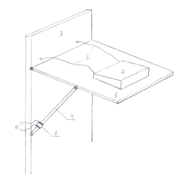
Ill. 4. A canopy, which generates electric power 1 – piezoelectric crystal, 2 – module with piezoelectric crystal for using the energy of raindrops, 3 – wall, 4- support, 5 – canopy, 6- cables.
We can use durable glasses in windows as “wind collectors” and place fastenings, which generate energy, at window casement (see the ill. 5a). In electromobiles we can switch fastenings: at car parks, when a vibration of glasses from wind is permissible, will be used fastenings, which generate electrical power, and in movement – usual fastenings in order not to disturb aerodynamic properties of electromobiles. Although by using the piezoelectric crystals we may obtain very small gap and switch will be not necessary. In a simpler variant (nontransparent shields) at car park we draw down the usual glasses and in place of them we put shields-generators, which lean on fastenings at windows casements. Same thing we can do at home. For example, at night, when windows must not transmit a light, we put such electrical generators in place of glasses or shutters (see the ill. 5b).
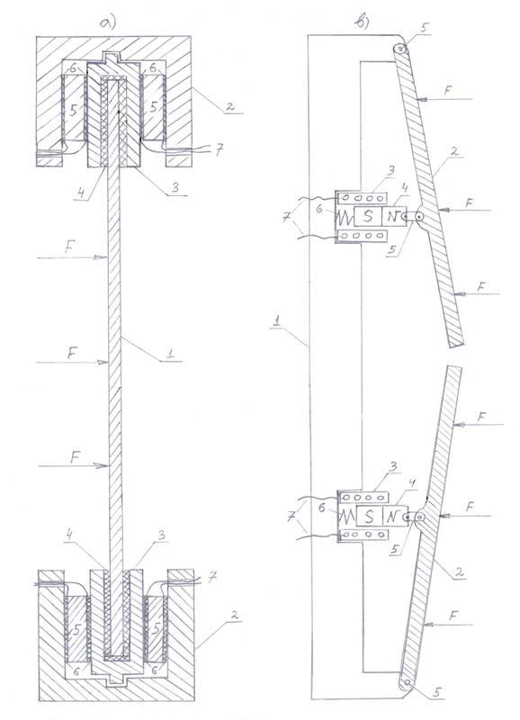
Ill. 5 a), b). Fastenings, which generate electric power at windows and shutters.
a) 1- glass, 2 – window casement, 3 glasses frame, 4 – thickenings, 5 – piezoelectric crystals, 6 – metallic plates, 7 – cables, F – strength of wind;
b) 1 – window casement, 2 – shutters, 3 – solenoids, 4 – magnets, 5 – swing joints, 6 – springs, 7 – cables, F – strength of wind.
The support, for example, a tripod for lamppost or a cellular antenna will generate electrical power, if in all its “legs”, divided in two parts, at the juncture, will be placed such fastenings, which generate electric power (see ill. 6). We can place a lamppost or a post of a cellular antenna into a buried in earth and fastened hollow cylinder with such electrical generators placed at its outer rim – this is an additional variant (see the ill.7). Lampposts with such “support“ can work independently, without power cables, because they swing from wind or from an oscillating of a road. Such lampposts must be very suitable in places without electric power stations or without a wiring.
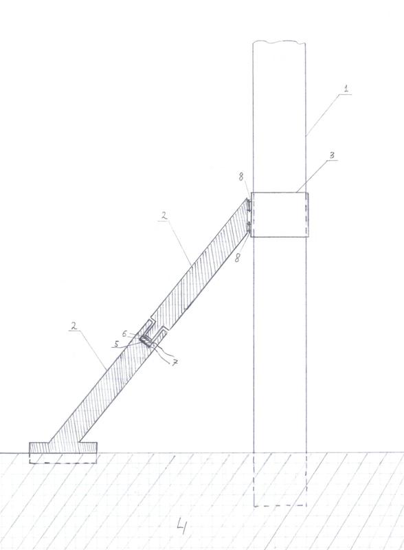
Ill. 6. A support of the post, which generates electric power. 1 – post, 2 – support, 3 – cylindrical rim, 4 – earth, 5 piezoelectric crystal, 6 – metallic plates, 7 – cables, 8 – swing joints.
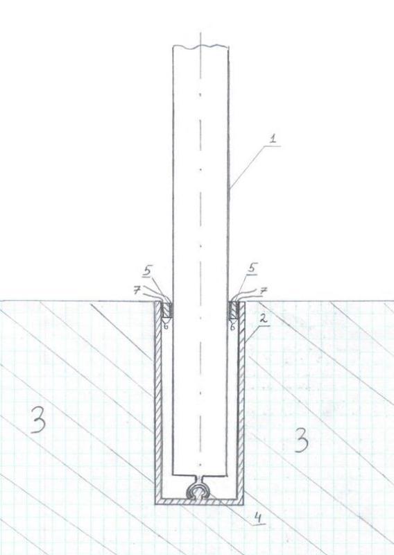
Ill.7. A post in cylindrical nest with linear generators at the edges. 1 – post, 2 – cylindrical nest, 3 – ground, 4 – swing joint, 5 – piezoelectric crystal, 6 – metallic plates, 7 – cables.
Additionally, linear generators make possible to use such natural “wind collectors”, as trees: trees’ branches very strongly swing from wind. But we must do it softly and cautiously in order not to damage trees. In my opinion, in this case it’s better to use solenoids generators and not generators with piezoelectric crystals. Solenoids with magnets and springs will ensure soft “relay”.
At the ill. 8a is represented an additional variant of a branch’s swinging. To fasten one rope (1) from electric coil at a stem or to attach it to an “anchor” (4) (marine type), which is buried in an earth, and other rope, connected with the magnet (2), to attach to a swinging branch. It’s not necessary to fasten the coil, only leave the connection with the branch (see the ill. 8b). Then a generator will work from a shaking, which will ensure a branch’s swinging from wind (and the spring (5) will prevent a falling of the coil).
In that way, although tourists will get electric power from trees, because a solenoid with a magnet and related electronic devices are not big and fit to a car trunk. At my opinion, such use of trees, if it accurate and gentle, will led not to reduction of trees’ quantity, but to their quantity growth. For example, the use of horses and animals from biological families of dogs and cats has led to their population growth and widespread. I don’t exclude, that will be chosen or bring some durable and springly breeds of tress with leaves as “sails”, which best fit to be “support link” of linear generators.
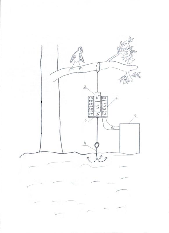
Ill. 8a). A use of branch’s swinging for generation of electric power. A generator is fastened at a stem or at a ground. 1 – solenoid, 2 – magnet, 3 – electronic unit, 4 – anchor, 5 – spring, 6 – cables.
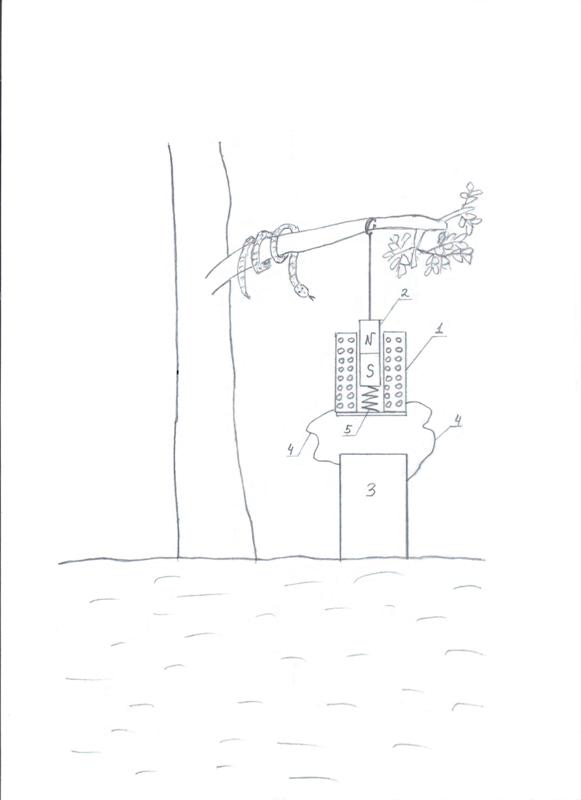
Ill. 8b). A use of a branch’s swinging for a generation of electric power. A work from a shaking. 1 – solenoid, 2 – magnet, 3 – electronic unit, 4 – cables, 5 – spring.
As for inflatable “working bodies” for linear electrical wind generators, surely, everyone has saw inflatable figures of human beings at filling stations and everyone has saw, that they don’t stay as statues. The wind is changing their forms very strongly. So, inflatable forms (it’s not necessary in form of human beings, it’s possible to build them in forms of balloons, ellipses, inflatable mattresses and so on) will “work” for a generation of ecologically clean electric power. Their advantage is that they by coming untied and moving by the wind can’t seriously injure human beings. At the ill. 9 is represented the use of air balloon as a working body for linear electrical wind generator of solenoid type, which works from wind. You need tie a magnet to a balloon and to anchor a coil, and it’s better to use elastic joints in order not to tear the balloon and not to injure the coil and electronic unit ( the systems of rectifying, smoothing an accumulation, which were mentioned above).
I will add, that it’s possible to use the energy of wind for the generation of electrical power at sailing vessels in places, where sails are attached (there is more useful fastenings, which generate electric power with piezoelectric crystals in order not to case big shifts) (see the ill. 10). The generated electric power will be used for accumulator’s charging as an additive energetic possibility in the case of calm, for a moving of electrical motors and for inner needs of vessels, for example, for lighting and refrigerators.
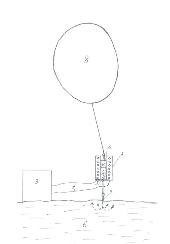
Ill. 9. An air balloon as a working body for a linear generator. 1- solenoid, 2 – magnet, 3 – electronic unit, 4 – anchor, 5 – spring, 6 – ground, 7 – cables, 8 – air balloon.
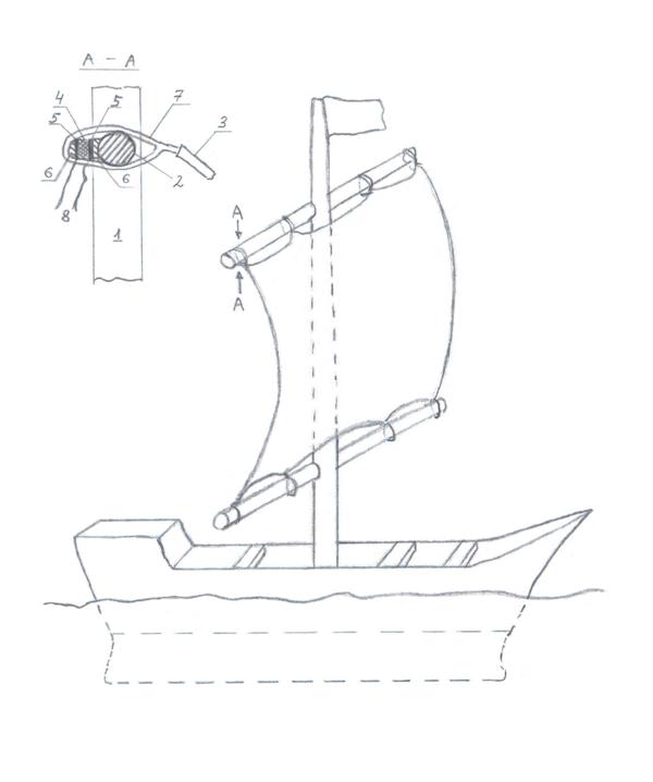
Ill.10. Sails’ fastenings, which generate an electric power. 1 – mast, 2 – yard, 3 – sail, 4 – piezoelectric crystal, 5 – metallic plates, 6 – laying bars, 7 – rope, 8 – cables.
Now we shall see, how to use the energy of sea and river waves. It’s possible to build such linear generators, where working bodies will be not big shields or other big geometrical figures, but small plates. Fastenings, which generate electric power, will remain same (with solenoids or piezoelectric crystals), but smaller. We shall place a set of such generators composed of plates at floating crafts at the level of a waterline (see ill. 11). They (generators) thanks to their small dimensions will not damage meaningfully a covering of vessels. It’s necessary to take care of flashing of generators and to place them under waterproof elastic covering. Waves biting at vessels (plates) will generate electric energy for motor (running gear) and for inner needs of vessels and it will make possible not to use bulky sails, which may turn over vessels. It’s hard to go against the wind with sails. It’s make possible not to use motors and internal combustion motors, which pollute the environment.
Ill. 11. Electrical generators with plates at vessels. 1 – shipboard, 2 – plates, 3 – solenoids, 4 – magnets, 5 – waterproof covering, 6 – springs, 7 – cables.
To use the energy of waves near a coast is simpler – you need attach solenoids to a pier, a landing-stage or other construction (see the ill. 12). In this case we need bigger shields and fastenings, because in this case streamlining will damage.
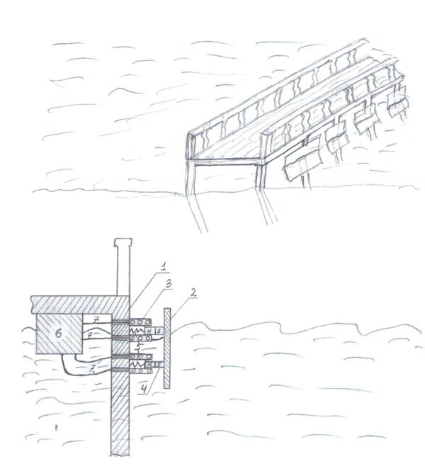
Ill. 12. Shields attached to pier with help of linear generators. 1- pier, 2- shield, 3 – solenoids, 4 – magnets, 5 – springs, 6 – electronic unit, 7 – cables.
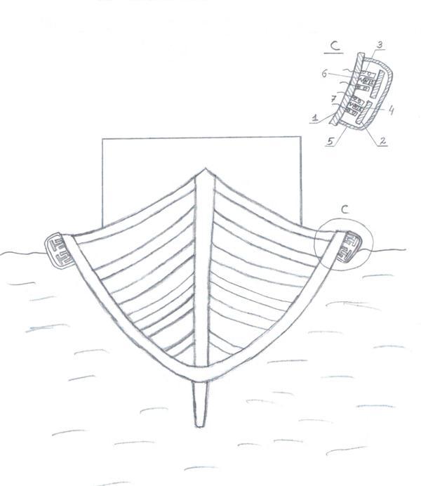
We have another option – to connect magnets with bobs in place of shields and to attach solenoids to supports of a pier or to its horizontal surface and, as another variant, “to anchor” solenoids. (see the ill.13).
Ill. 13. A bobs’ system of a generation of electric power from waves’ energy. 1- pier, 2 – bobs, 3 – solenoids, 4 – magnets, 5 – springs, 6 – electronic unit, 7 – cables, 8 – ropes, 9 – anchor, 10 – water, 11 – bottom.
There is another option – to transform the energy of waves to an electric power. For this purpose we need place at a floating craft bigger copies of generators, represented above, which work from a shaking, as at Faraday’s flashlight and at bicycles headlights. There is another variant – to build hermetic waterproof floating “capsules”, which include transformers and accumulators. In an edging should be conducting zones for two conductors and if there is an accumulator, then should be a switch. It’s possible to throw such capsules to waves’ mercy near a coast or to convey them after vessels.
For this purpose (the using of waves’ energy) is designed a raft – an electrical generator, which is represented at the ill. 14. Waves will supply a movement of bobs (1) relative to each other, and this with help of supports (2) with swing joints (3) will cause a movement of magnets (6) relative to solenoids (5). It should be recalled, that linear generators attached to supports with swing joints consist of magnets, solenoids and springs (7). Accumulator (8) and electronic unit (9) are confined in common hard cover (10), hanging on ropes from supports. The system of supports, swing joints and springs doesn’t confine completely movements of bobs relative to each other, but doesn’t give to raft to fall to pieces. Relative movement of magnets and solenoids will cause a generation of electric power in solenoids’ windings, which will be conducting through cables (are not represented at the ill.) to the electronic unit. There it will go through rectifying and smoothing devices and will go into the rafts’ accumulator or through the cables (are not represented) will be conducted to a cost or to a vessel, towing the raft, for its energetic needs.
For more full use of all direction of waves activity it’s possible to build a conglomerate of all such rafts, placing them at optimal angle relative to each other or to build at one raft composite, more complicated, than at the ill. 14, system of supports, swing joints and springs, taking into account all possible relative shifts of bobs.
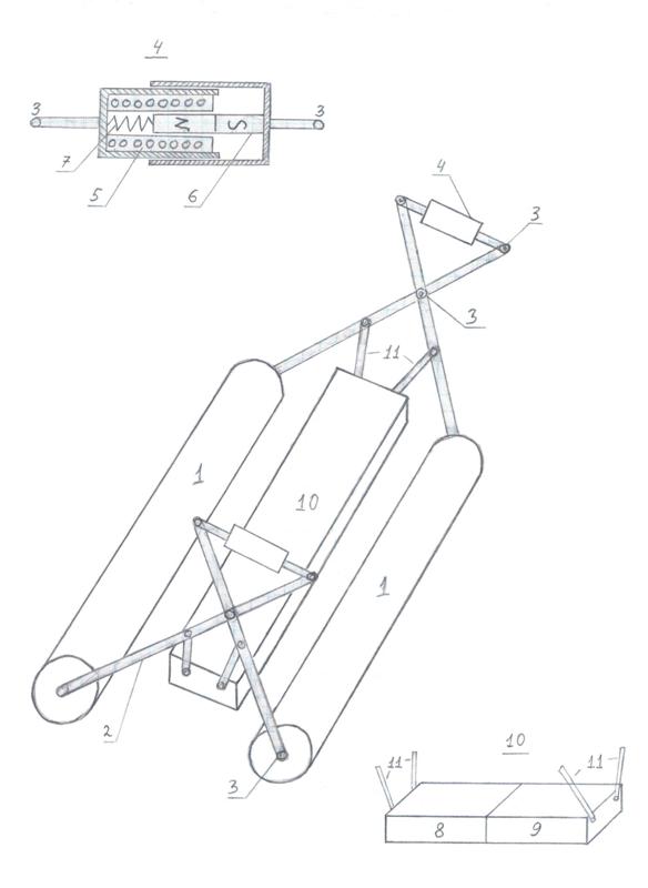
Ill. 14. A raft - electrical generator. 1 – bobs, 2- supports, 3 – swing joints, 4 – linear generators, 5 – solenoids, 6 – magnets, 7 – springs, 8 – accumulator, 9 – electronic block, 10 – hard covering, 11 – ropes.
Linear generators match to the use of energy of differences of water levels in rivers and waterfalls, by ebbs and flows. They will work in place of turbines. According to preliminary estimates, the effectiveness of such generators is smaller, but it’s simpler to build linear generators and related devices, because of turbine generators are revolving and they demand a very precise production, a balancing and good bearings. At the ill. 15, 16, 17 and 18 are represented the possible variants of the use of linear generators.
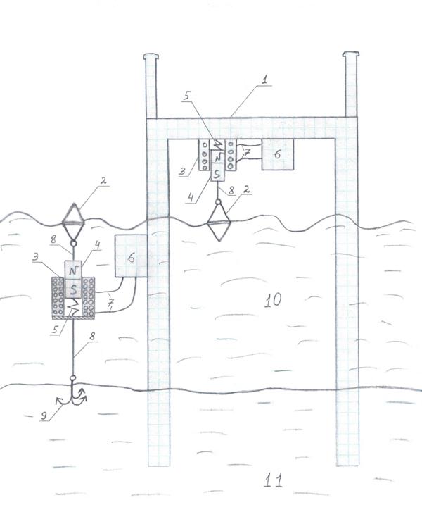
The scheme below is the simplest for build (ill. 15). You need fix the solenoid at a coast (very good at a bridge) of a river or a waterfall and to tie the bob, sinking in water (2) to the magnet (6). If a flow is turbulent, and there is a fast river or waterfall, the bob will oscillate and will conduct the oscillation to the magnet, and electric power will be generated. The magnet and the bob will not swim away, because of the magnet is fixed to the bottom of the coil (9) of the solenoid (7) with the spring (8). This scheme is very similar to the scheme above for the use of waves’ energy (see the ill.13).
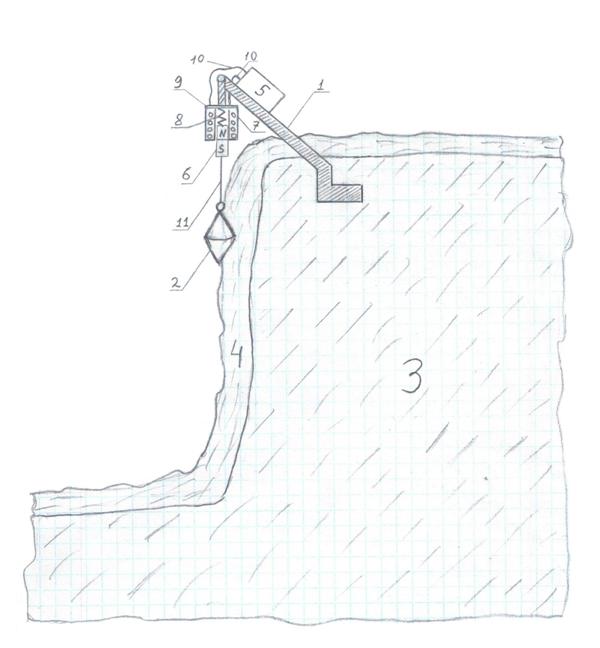
Ill.15. A bobs’ system of a poweРис.15. Поплавковая система выработки электроэнергии на речке или водопаде. 1-стойка, 2-поплавок, 3-берег, 4-поток, 5-электронный блок, 6-магнит, 7-соленоид, 8-пружина, 9-днище бабины соленоида, 10-проводаr generation from a river or from a waterfall. 1- support, 2 – bob, 3 – coast, 4 – flow, 5 – electronic unit, 6 – magnet, 7 – solenoid, 8 – spring, 9 – the bottom of the solenoid coil, 10 – cables, 11 – rope.
At the ill. 16a is sufficiently good represented a well-known system. To the cumulative bowl is falling from above a permanent water flow, for example, from the branch duct (2) from a river. When the bowl is filled, the hydrostatic pressure on the tube’s edge (3) in this vessel will be bigger then the threshold of locking ( in the tube there is air), water will begin to pass through the tube and will flow out on the linear generator (4), which is placed under it. The water level in the bowl will fall under the curved tube’s edge (h min) and air will “lock” it again. Because of entrance of water from above the vessel will be filled up to the level (h max). In this situation the hydrostatic pressure is able “to unlock” the tube and so on. This ensures an intermittent falling of water on to the linear generator, and this is necessary for a generation of electric power. After the work done water will stream down to the collector (5) and from there through the relevant channel (6) into the river, but at the more low level.
At the ill. 16 b and c are represented linear generators, designed for the use of an intermittent liquids’ falling on them. At the ill. b – a generator of solenoid type, there is the hatchback cuvette (1) for an accumulation and a sinking of water are fast attached to the magnet (2), placed in the fastened solenoid (3). The spring (4), attached to the bottom (5) of the solenoid’s coil, supports the magnet from below. At the ill. c – piezoelectric l type. There is the same cuvette (1) leans on piezoelectric crystal (2), which generates the electrical power.
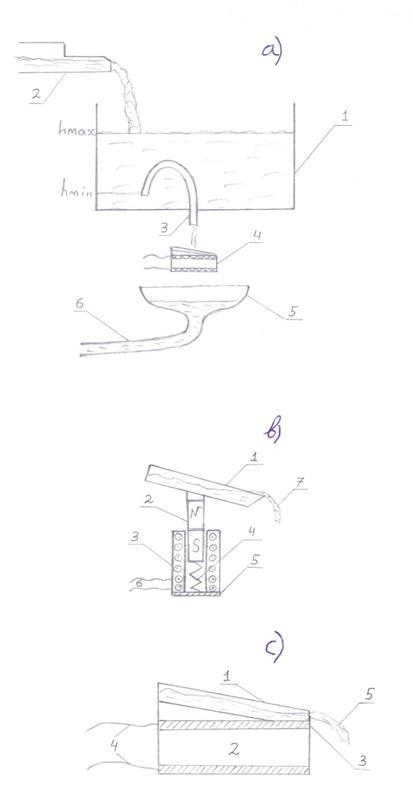
Ill. 16 a) b) c) The use of the difference of water levels in nature for power generation. a) 1- cumulative bowl, 2 – branch duct from the river, 3 – tube, 4 – linear generator, 5 – collector , 6 – the returning to the river channel; b) 1-hatchback cuvette, 2 – magnet, 3 – solenoid, 4 – spring, 5 the bottom of the solenoid’s coil, 6 – cables, 7 – water; c) 1- hatchback cuvette, 2- piezoelectric crystal, 3 – metallic plates, 4 – cables, 5 – water.
At he ill. 17 is represented the device with the same destination, but from the other type – this is rotating (in the vertical plane) bowl (1) with a swing joint (2). This bowl has different centers of gravity in the filled and in the unfilled states. If the bowl is unfilled, it in the state of equilibrium: it is leaning on the swing joint (2) and the support (3). The vertical from its center of gravity passes through the bearing area. With the filling of the bowl with water, for example, from the branch duct (10) from a river its center of gravity is shifting. When the vertical from the new center of gravity (C2) will exceed the boundaries of the bearing area, the bowl will begin to turn over. With the turning over the vertical from the center of gravity will exceed the boundaries of the bearing area more and more. In the end the liquid from the bowl will pour on the linear generator (5) and then into the collector (7) and into the channel which return water to a river (8). The empty bowl will return to the starting position of stable equilibrium. Water will fill the bowl and the cycle will be repeated.
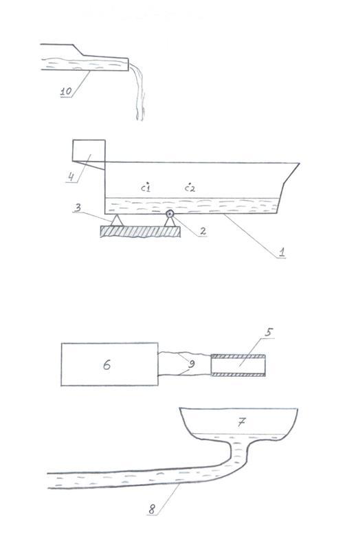
Ill. 17. An overturning bowl-generator. 1- bowl, 2 – swing joint, 3 – support, 4 – ballast, 5 – linear generator, 6 – electronic unit, 7 – collector, 8 – returning to the river channel, 9 – cables, 10 – branch duct from the river.
Further, at the ill. 18, is represented a device of pendulum type, which makes possible to transform the energy of falling water into electric power. From constantly filling bowl (1) (from its bottom) comes the flexible hose (2), which is oscillating together with the pendulum (3). The pendulum works, for example, from an electric motor with a reducer. The hose alternately pour out water on several linear generators (5). The generated power through rectifying elements and smoothing elements in the electronic unit (6) recharges the accumulator (7). The accumulator supplies power to the motor and the remaining part of the power gives to the paying load (8).
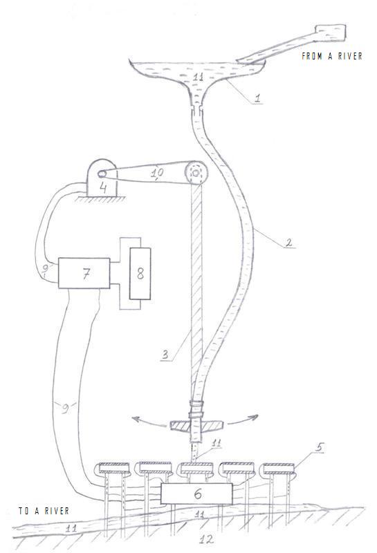
Ill 18. A pendulum type of power generation from the difference of water levels. 1 – cumulative bowl, 2 – flexible hose, 3 – pendulum, 4 electric motor with reducer, 5 – linear generators, 6 – electronic unit, 7 – accumulator, 8 – paying load, 9 – cables, 10 – belt transmission, 11 – water, 12 – ground.
It’s possible to design many additional possibilities of the use of linear generators and many variants of their and supplementary devices’ constructive building. I hope that these generators will take their place in the sphere of a generation of ecologically clean power.
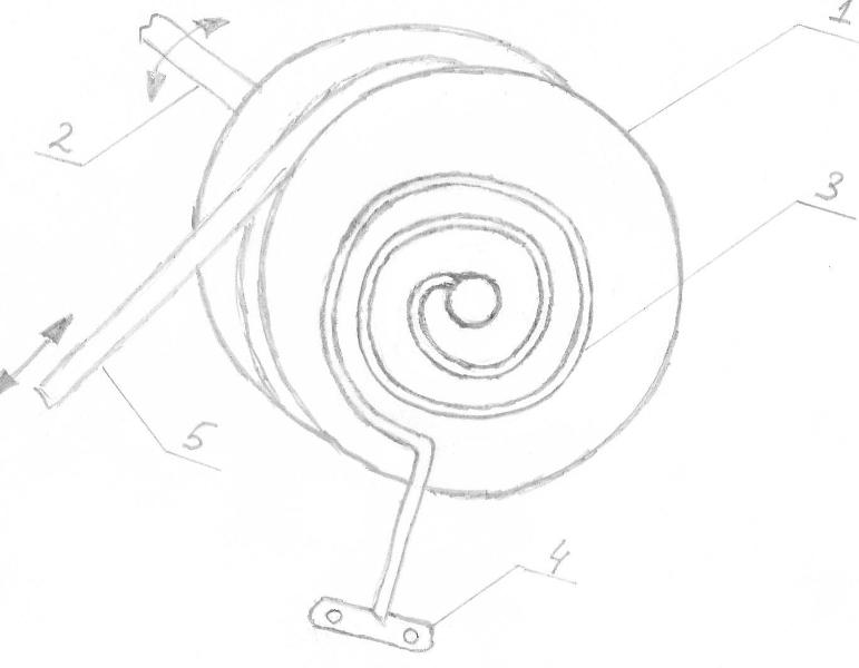
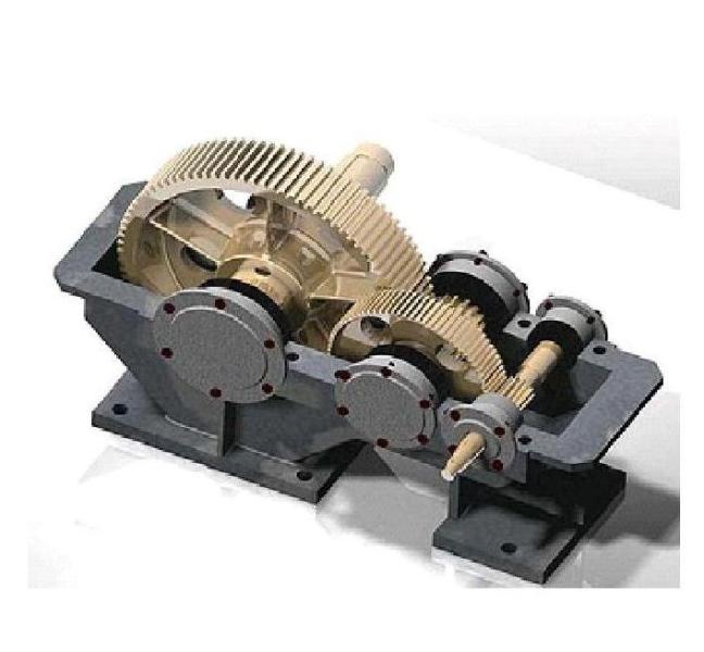
If from any causes it’s impossible to build or to apply these generators or there are work usual generators, which work from rotation, anyway possible to use some linear movements, for example, from branches’ shaking from wind with sufficiently great amplitude or movements of bobs or balloons, because of mechanical transmissions, which can to transform linear movements into rotating movements. For example, rack & pinion gear (see ill. d), screw-gear (as in humming-top) and belt transmission with coil (see ill. a). We spool the belt, fishing line or cable at a coil and attach to it restoring spring, for example, spiral spring**** In addition, it’s desirable after the getting rotation at the some axle to place after it increaser (see ill. B) for more rotations, and to attach dynamo to its outlet axle, since dynamos are designed for effective work with great speeds of rotation. For a generation of more power in this way we need use a transmission as increaser as in autos and bicycles and switch speeds (gear-ration) depending on the power of wind or waves in the current time.
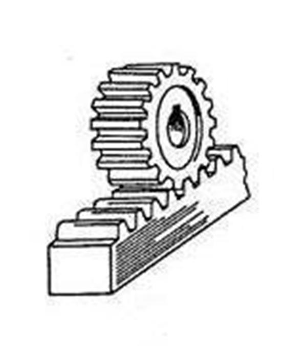
ILL. D Rack and pinion gear system
|
|
|
|
|
|
||
|
|
|
|
|
|
Ill. B. Increaser gearbox.
If we shall estimate, which part of the airspace near a ground is influenced by wind and doesn’t work for power generation and what is the square of water’s surface with waves and waterfalls, which don’t work (not to mention sunrays and geothermal springs), we shall see, that a generation of ecologically clean power has a great future.
Notes:
*Reference to Faradays Flashlight:
http://www.youtube.com/watch?v=tHg51GOzCXU ; http://www.sdelaysam-svoimirukami.ru/284-vechnyi_fonarik_ili_fonarik_faradeja.html
**It should be noted, that for a generation of power in solenoid it’s not necessary push in and pull out the magnet (at the current time the most powerful magnets are neodymium). It’s sufficiently and not less effectively move near and move away the magnet from the electrical coil, if there is the core in the coil, it’s better – ferrite core.
*** In accordance with Lenz’s law
****There can be useful a part of spinning or seat belt. It’s possible to build a combination of their elements.
Сконвертировано и опубликовано на http://SamoLit.com/